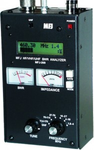
 As an added service to members “The Society” has available to borrow a MFJ-269 antenna analyser. This analyzer allows you to verify that the impedance of your antenna is correct thus ensuring all your power is actually radiated. A request form will soon be available in the members section of this site
Covers 1.8 to 170 MHz and 415 to 470 MHz — an MFJ-269 Exclusive! It includes all the features of the MFJ-259B, the worlds most popular SWR Analyzer plus much more! Large easy-to-read two line LCD display and side-by-side meters clearly display your information Built-in Ni-Cad/Ni-MH charger circuit, battery saver, low battery warning, smooth reduction drive tuning. Use as signal source for testing/alignment. Built-in CoaxCalculator — calculates coax line length in feet given coax length in electrical degrees and vice versa for any frequency and any velocity factor (great for building matching sections and phasing lines) — an MFJ-269 Exclusive! New 12-bit A/D converter gives much better accuracy and resolution than common 8-bit A/D converters — an MFJ-269 exclusive. Super easy to use! Just set the bandswitch and tune the dial — just like you transceiver.
1.8 to 170MHz range features
MFJ-269 gives you a complete picture of you antenna. Read antenna SWR and Complex Impedance 1.8 – 170 MHz. Built in frequency counter. Read Complex Impedance as series equivalent resistance and reactance (Rs+jXs) or as magnitude (Z) and phase (degrees). Also read parallel equivalent resistance and reactance (Rp+jXp) — and MFJ-269 exclusive! You can determine velocity factor, coax loss in dB, length of coax and distance to short or open in feet.
You can read SWR, return loss and reflection coefficient at at any frequency simultaneously at a single glance. Also read match efficiency. Also read inductance in UH and capacitance in pF at RF frequencies. You can measure SWR and loss of coax with any characteristic impedance from 10 to over 600 Ohms, including 50, 51, 52, 53, 73, 75, 93, 95, 300, 450 Ohms — an MFJ-269 exclusive! For more information see MFJ-259B. New 415 to 470 MHz Range features. Just plug in your UHF antenna coax, set the frequency and read SWR, return loss and reflection coefficient simultaneously. You can read coax cable loss in dB and match efficiency.
You can test and tune stubs and coax lines. You can manually determine velocity factor and impedances of transmission lines. You can adjust and test RF matching networks and RF amplifiers without applying power. Has easy-to-read LCD logarithmic SWR bargraph and SWR meter for quick tuning.
Take it anywhere
Fully portable take it anywhere — remote sites, up towers, on DX-peditions. Built in “N” connector Free N-to-SO-239 adaptor. Use 10AA Ni-MH or Ni-Cad or alkaline batteries (not included.) or 110VAC with MFJ-1312D, $14.95


